Rotary Encoder construction
-
Machining
Take the 6mm shaft, bearing sleeves and threaded inserts to Phil's place for machining.
Tea and coffee provided. BYO lunch if needed.
-
Building the Rotary Encoder
Beginning with the 3D printed central boss: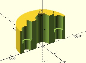
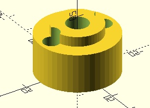
CAREFULLY press the threaded inserts (small end first) into the larger end of the smaller holes. The flange on the threaded insert should seat against the step in the smaller hole.
VERY CAREFULLY press the bearing sleeves into the central hole.
Use a short piece (16mm) of the 6mm rod (deburred of course) to keep the sleeves aligned.
Remove the alignment piece.Apply a small amount of oil to the sleeves and wipe off the excess.
Insert the 6mm shaft and fit the circlips.
Take a 40 to 50mm x 2.0mm diameter nail. Cut off the head and remove burrs.Fit the encoder disc to the nail and insert into the hole in the shaft.
Do a trial assembly to check alignment. The nail will initially be too long.
Trim a little off the nail (not too much, you can't add it back on).
Repeat the trial assembly and re-trim until it runs smoothly.
Disassemble, apply small drops of superglue and re-assemble for the final time.
Congratulations, you now have your tuning encoder.