Si5351 VFO
You should grab a copy of the Si5351 VFO Configuration notes.
This is all about my tinkering with the Si5351 in an attempt to make a continuously tuning VFO for a home made radio, based on the BitX design.
First I'd like to briefly show three different projects in which I have used this chip.
All use Microchip PIC processors, programmed in assembler (because I like assembler)
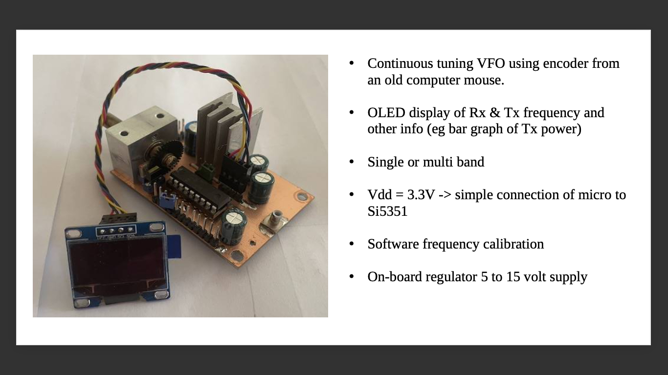
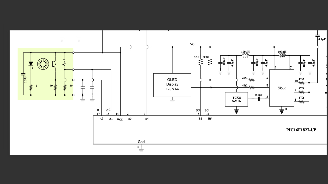
This VFO is the prototype one used in my BitX like radio (same schematic and software - different circuit board)
The software for this radio has a minimum tuning step of 1Hz, with acceleration of up to 128Hz per step if the tuning control is moved rapidly.
The software implements multiple bands, two BFOs, bar graphs for battery voltage, transmitter RF output voltage and heatsink temperature. I am happy to give a copy to anyone who wants to experiment with this VFO.
And, here is the VFO schematic (with some wrong component values shown).
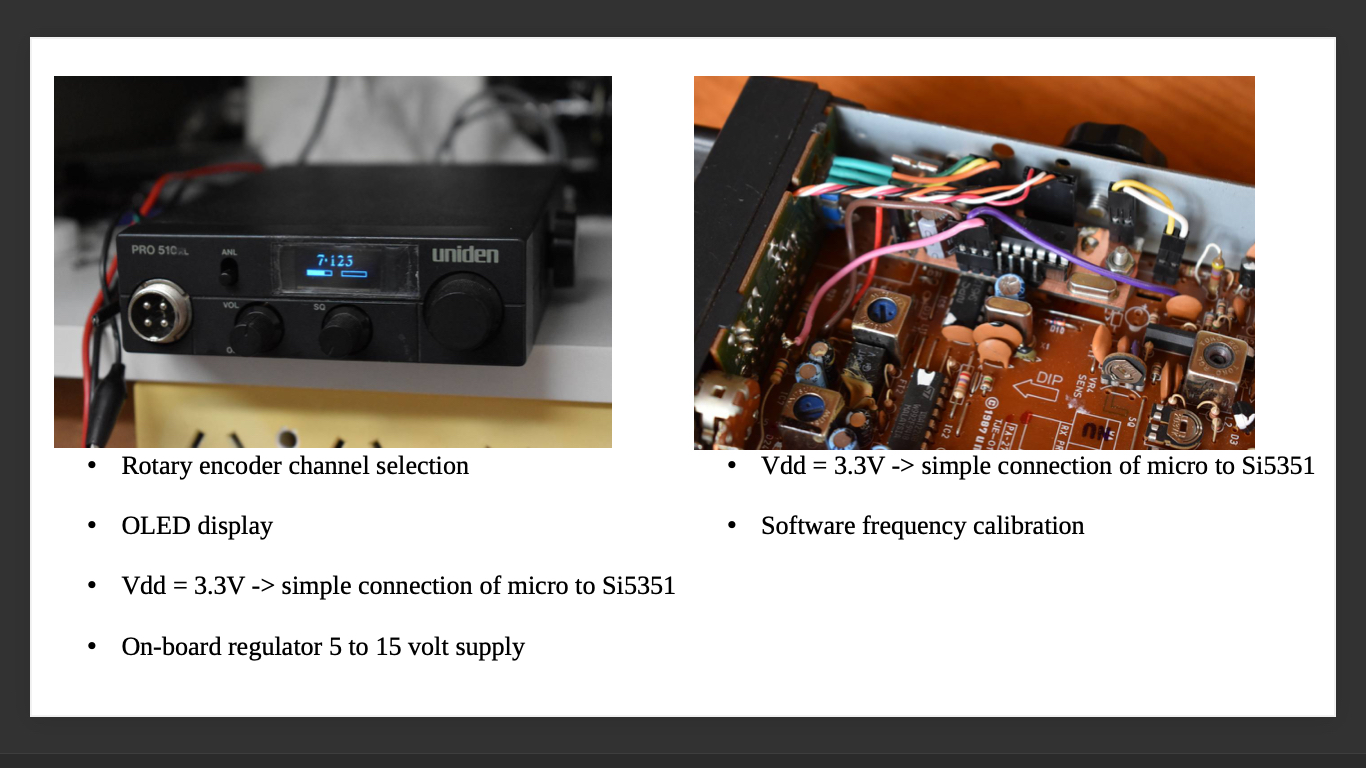
Here is a CB radio that has become a 7MHz AM radio, purely for the 1st April SOTA AM day.
The receiver works fine, but I still have some unfinished business with the transmitter.
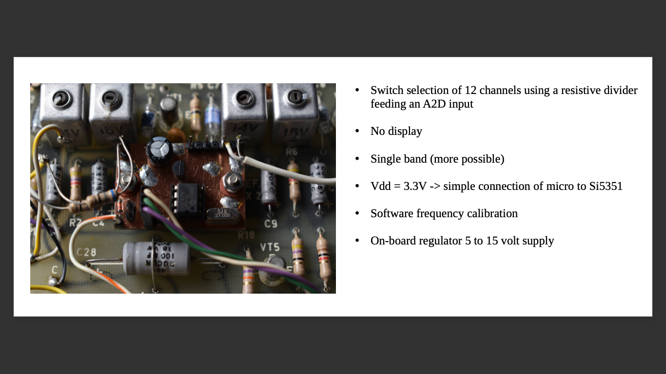
The final project simulates a bank of 12 crystals in an ancient AWA Forest Phone.
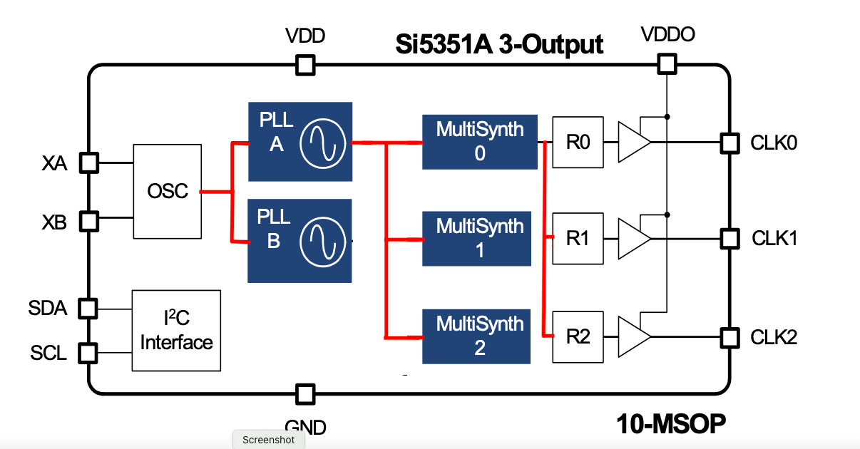
So, lets have a look at the Si5351
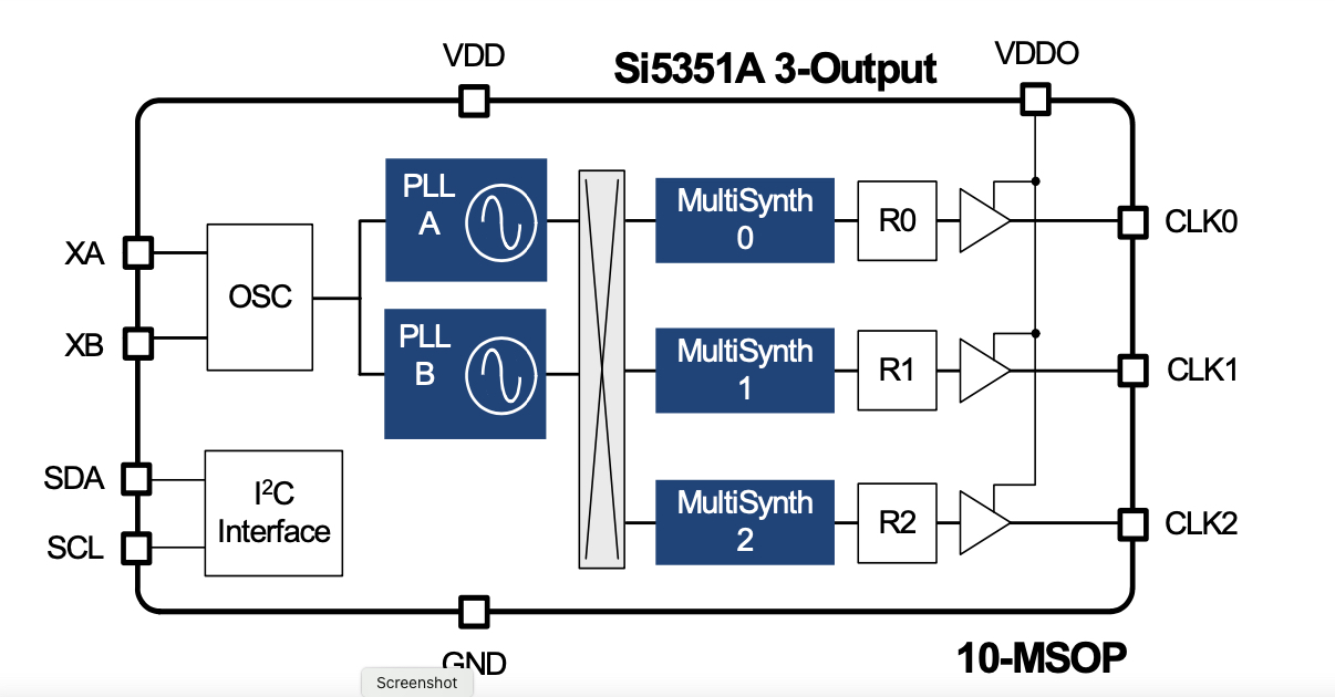
The PLL blocks contain a 600 to 900 MHz VCO, phase locked to a 25 to 28 MHz crystal.
The PLL feedback is via a Fractional N divider. The VCO frequency is equal to the crystal frequency multiplied by the divider ratio.
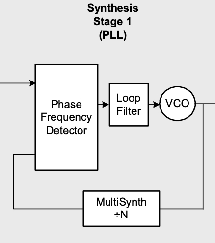
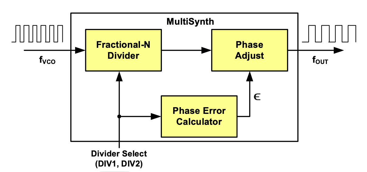
The VCO outputs can be routed to three MultiSynth blocks, each one being a Fractional N divider like the divider in the PLLs.
Operation of the Fractional N dividers is described in US Patent 7295077.
It seems that the division ratio is changed on a cycle by cycle basis then corrected somewhat to make the output frequency close to the desired value.
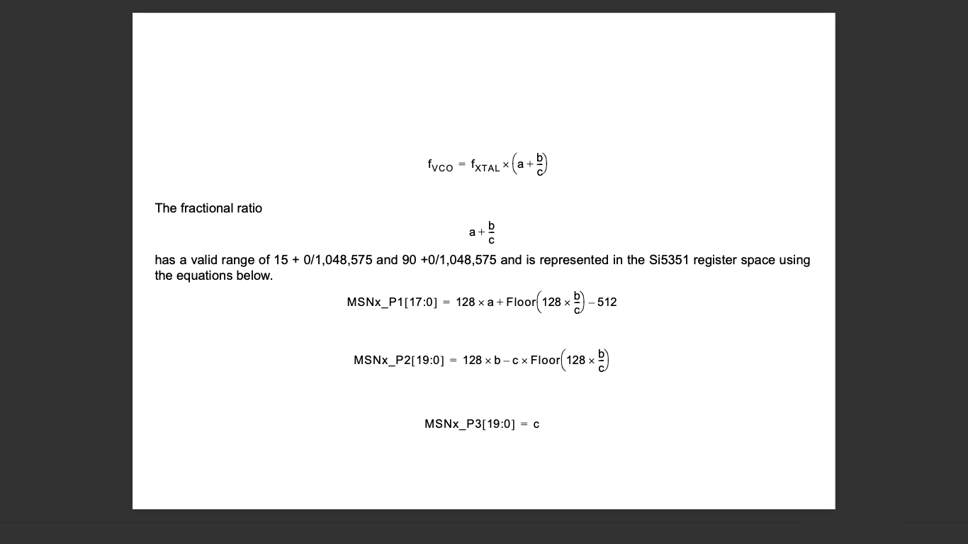
And here are the equations describing the setting of the division ratio. Note that both the PLL divider an the MultiSynth dividers appear to use the same design.
Fractional N division can be quite noisy. Here are spectra comparing MultiSynyth outputs for both Fractional and integer division (of the same value).
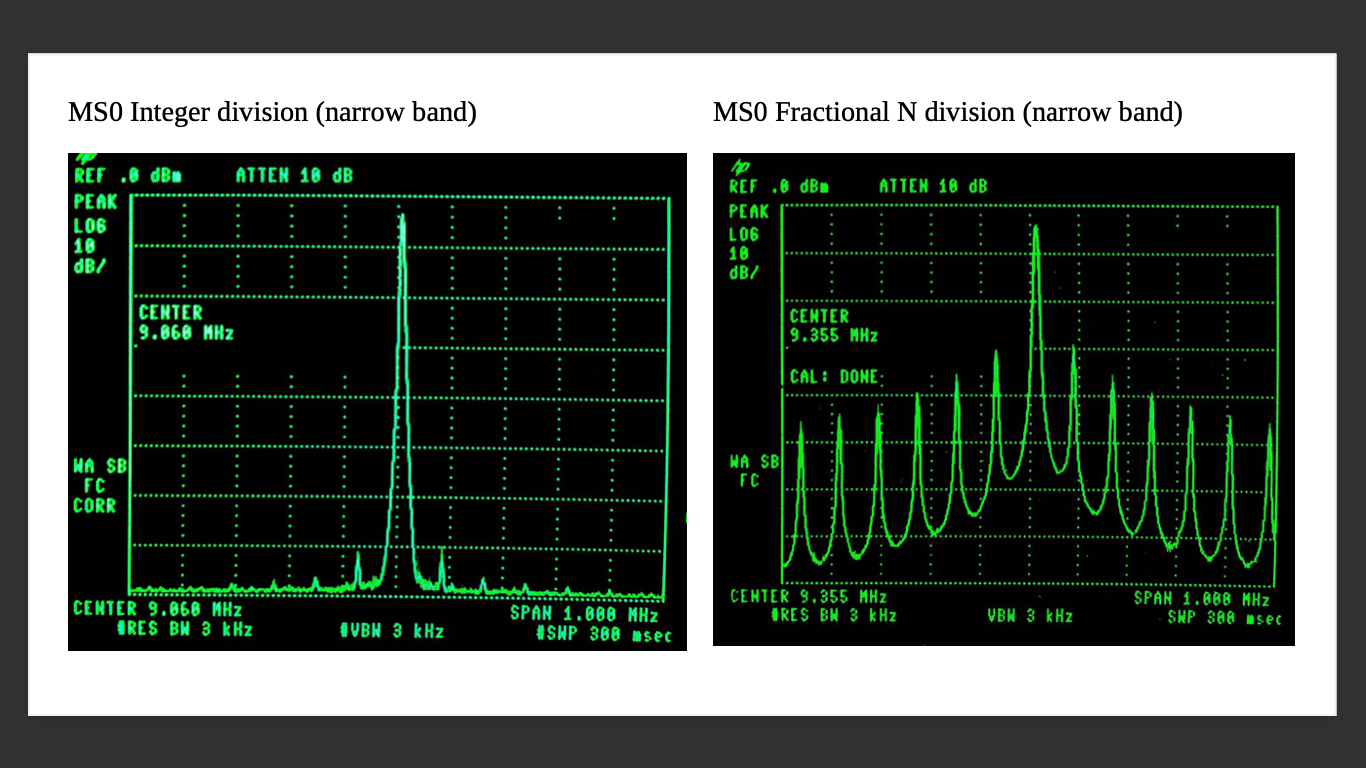
When used in receive VFO service these extra sidebands can appear as birdies and/or a raised noise floor (by each mixing some band noise into the IF passband)
I did try to use PLLa and MultiSynth0 to produce a VFO and PLLb and MultiSynth1 as a BFO, but run into troubles. Others seem to have succeeded, but I found the BFO signal to be full of birdies from the VFO.
Getting to the bottom of this is A Work in Progress(tm). I opted instead, to use a crystal oscillator for the BFO and to use the Si5351 to generate only the VFO signal.
To try to minimise birdies, I programmed both PLLs to generate the same frequency. All MultiSynths were set to the same EVEN INTEGER division ratio, resulting in the signal flow shown below.
This reduced the birdies to a very low level.
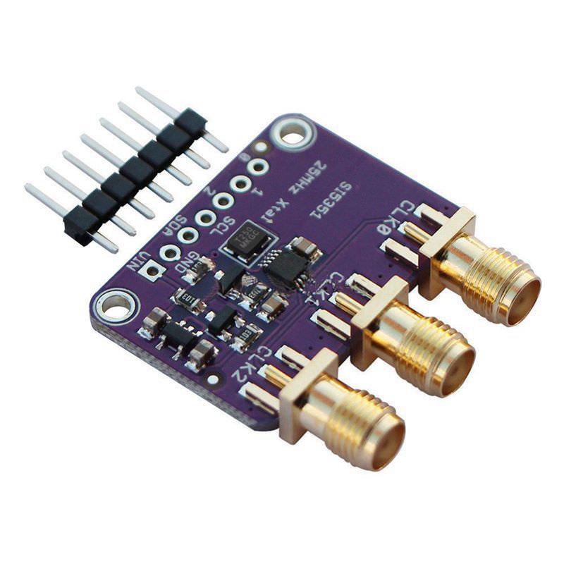
As seen in the advertising at the top of the page, all my projects have used home-made circuit boards with the Si5351 hand soldered. This is not an easy task as the pin pitch is just 0.5mm and solder bridges are almost inevitable. (And there have been a couple of disasters).
Also, the bare chip only handles supply voltages up to 3.3 volt. It can be directly connected to a micro running of a 3.3 volt supply.
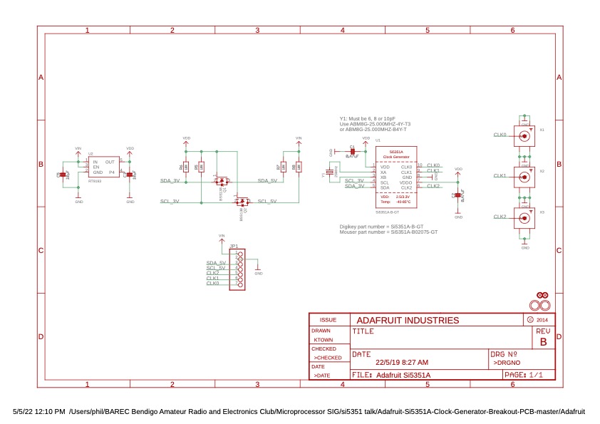
For 5 volt micros, Ebay and AliExpress vendors currently flog Si5351 boards based on the Adafruit design. These incorporate
on-board voltage regulator and I2C level shifters making them suitable for 5 volt as well as 3.3 volt systems. When controlled from an Arduino Nano or similar,
these should be easy to get going. (I haven't tried this yet).
This link looks like a good place to start