Programming the Intermediate frequencies
As programmed, the counter "thinks" the IF frequency is zero. As a
result it displays the input frequency directly.
The counter can add or subtract any one of three different "stored" IF
frequencies. All you have to do is "program" the counter as follows.
(Your radio will need to have an oscillator, on the desired
intermediate frequency - the BFO is the ideal choice. If your radio is
AM only, you will need to use a signal generator set to the centre of
the IF passband.)
To program the lower BFO frequency (note, I am avoiding the use of the
terms USB and LSB here), set your BFO to the lower frequency and
connect the counter to it. Connect pin 12 of the PIC chip to ground.
(the PIC has internal pull-up resistors) This tells the PIC that you
have put the BFO on its lower frequency. Now connect pin 10 to ground
(a temporary switch or push-button is ideal). After about half a
second, the display will show the actual BFO frequency followed by
PRG. When you are happy that the displayed frequency is OK, disconnect
pin 10 from ground. After half a second, the PIC will copy the
displayed frequency to its internal EEPROM (you can do this up to
10,000 times ;-). The display should now show 0.00000MHz or
something around 67 MHz. (This happens if the input frequency drifts. Don't
panic. All is OK.)
To program the upper BFO frequency, disconnect pin 12 from ground and
connect pin 13 to ground. Connect the BFO to the counter input (as
above). Now connect pin 10 to ground, wait a second or two (as
above), disconnect pin 10 from ground and wait another second or two.
To program the third offset, proceed as above, but with both pins 12
and 13 grounded.
To persuade the PIC to calculate the correct frequency, connect the
counter to your first Local Oscillator. Connect pin 12 or 13 (or both)
to ground, appropriate to your BFO frequency (as above). Leave pin 10
floating (it has an internal pull-up resistor).
Finally, pin 11 may be pulled low to indicate that you want the
displayed frequency to equal the sum of the Intermediate Frequency and
the Local Oscillator frequency. Leave pin 11 floating if you want to
subtract one from the other and display that. The PIC will figure out
which way to do the subtraction.
For AM reception (in conjunction with SSB), leave both pins 13 and 13
floating. The PIC assumes the IF is half way between the two BFO
frequencies programmed above (so you have to program both).
For AM only , you can tie both pins 12 and 13 permanently low, and
program the IF frequency once (using a signal generator set to the
centre of the IF passband).
For radios which use the dog's breakfast approach to local oscillator
& BFO selection, pins 11, 12 and 13 can be pulled low or floated at
any time. The PIC checks all them each measurement cycle, so will
respond almost immediately to band changes, BFO changes and changes
between adding and subtracting.
The following simple inverter circuit can be used to connect the PIC
pins 11, 12 and 13 to "high" voltages, without blowing anything up
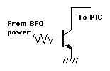 The resistor is sized to give a base current of about 20 to 100uA.
Something around 10 to 47KOhm per volt of input should be OK. Any small
NPN silicon transistor should be suitable. The applied voltage must
fall to below 0.6 volt to turn the transistor off (thereby, floating
the PIC pin high).
The resistor is sized to give a base current of about 20 to 100uA.
Something around 10 to 47KOhm per volt of input should be OK. Any small
NPN silicon transistor should be suitable. The applied voltage must
fall to below 0.6 volt to turn the transistor off (thereby, floating
the PIC pin high).