The resolution of the original design could (in theory) be +/- 0.04pF and +/-3nH. The software deliberately limits the resolution to +/-0.1pF and +/-10nH
Being in great need to accurate measure small value capacitances and inductances i found your article "A Surprisingly Accurate Digital LC Meter".
I didn't have any experience in using or programming any PIC microcontroller, so it took me 2 long days to have the PIC programmer and the LC Meter completely built, and running. The information on your page was very helpful and containing all elements needed to succeed. I used the version of software modified by Andreas Winter. The LC Meter worked great from the first moment but i was unhappy about the fact that it wasn't able to measure or compare inductances smaller than 10nH.
Understanding the limitations of program memory capacity and accuracy of 24bit floating point routines i decided to push it to more accuracy forcing the oscillator to have greater deviations of frequency for small inductances. I decided also not to modify gate time so F1 was a constant. So L1*C1 became also a constant. From 1/F3 = 2*PI*sqrt(C1*(L1+Lx)) is obvious that the choice o a bigger capacitor C1 and a smaller L1 will solve the problem. So i added a second oscillator of 10000pf and 6.4uH, switchable by software through PORTB(5) which wasn't used. Schematics of the LC meter can be found here and here. You will notice a second calibration capacitor of 10000pF (required anyway to have sufficient accuracy in the calibration phase). At this moment i was able to measure 10 times more accurate inductors, without any modification of the program, only being careful to mentally move one digit to the left the dot point of the result and switching scales manually.
A also added a simple short pulse formatter for RESET, giving a pulse of about 3us at any kind of push of the "CAL" button, to avoid the unpleasant blockage of the display. I used a 4 nand trigger schmidt MC4093 so i took advance of the 2 remaining gates to "clean" and gate the oscillator output. (Notice that the gate signal from PORTA(0) needs to be reversed). I added a second pushbutton (instead of "setup" jumper) and i named it "scale". This button has also it's setup role if you hold it while pushing "CAL" or at power on. It enters a test sequence showing 4 frequencies, F1, F2 for the original oscillator and ^F1, ^F2 of the "extended" oscillator. The move from one frequency to another is done by pushing once "RANGE" button. Exit from test sequence is done by pressing "CAL". During normal operation, any press of "RANGE" switches the oscillator and forces a calibration. Pressing "CAL" will do a calibration without switching oscillators.
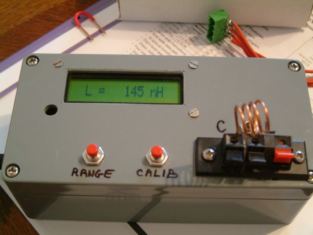
Display shows if the meter is in original or "extended" range by printing "^C" and "^L" when the second oscillator is selected. ^C mode extends 10 times the value of capacitors measured. I had fun writing a unique routine to display the results with the right units and dot points for all 4 scales and for the oscillator frequency and that freed the space for the test sequence and for something new that i added. I checked the accuracy of the meter using 4 different professional meters and i noticed that the errors are quite constant for every range but if you fix the error using a trimmer for the Ce, you can fix only the measure of L or C but the other will still have an error. This phenomena and some nonliniarities are due to the imperfection of "real" C1 and Ce which tend to include small inductances.
So i added in EEPROM 4 constants, one for each range to correct the result. For example if you notice a 3% difference in minus on ^C scale compared to a "trustful" meter you give to Cext constant in EEPROM the value 103 to correct it. the initial result will be multiplied by 103 and then divided by 100 and the CL Meter will show the correct value. An uncorrected scale will have the correction constant = 100.
The software for this version of the LC meter can be found here
Meantime i took some time to comment the program so i attached to this mail the commented one. It might be more useful for somebody trying to use it.
I noticed that the theoretical resolution of measure considerably depends on L1C1 oscillator frequency F1.
Cmin = (F1^2/(F1-1)^2 - 1) * C1 and Lmin = (F1^2/(F1-1)^2 - 1) * L1
For C1 = 1000pF and F1 = 550000Hz Cmin = 0.036pF ; theoretical Lmin = 3nH
For C1 = 1000pF and F1 = 600000Hz Cmin = 0.023pF ; theoretical Lmin = 2.2nH
So i tuned the inductances at setup time to have F1 and ^F1 = 60000, considering this the biggest frequency safe enough not to overflow the counter due to temperature changes in value of components.
For second oscillator:
C1 = 10000pF and F1 = 600000Hz the theoretical Lmin = 0.22nH This is sufficient to have a stable value of measured inductance in the 1nH field of result.
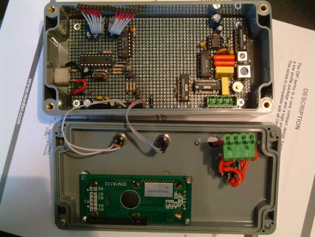
I used the same "donnut" kind board with soldered wrapping wire to build the LC Meter and it is very stable
Most care must be done choosing C1 and Ce. I checked with some different kinds of condensers and some includes significant inductances due to manufacturers' technology. A good way to select the best "model" to use is to switch in L mode and measure same inductance with more models of C1 having same capacitance value. The one showing the greatest value of inductance is the "cleanest" model. This is very simple to demonstrate considering that on calibration phase the oscillator gets a Ce and a Le in parallel with C1 and L1.
Best Regards
Cristi