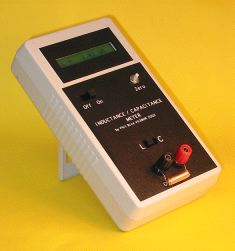
An inductance / capacitance meter by Phil Rice VK3BHR
Almost as published in Amateur Radio magazine, April 2004.
Measuring range is from 0 to >0.1uF for capacitance and 0 to >10mH for inductance.
Expected accuracy is +/- 1% of reading +/- 0.1pF or +/- 10nH
Frank Winter VK4BLF has made a nice printed circuit board for this meter. (It's much nicer than my unit which was constructed on "dot matrix" board.) See http://members.optusnet.com.au/frankwinter/ for details. Frank also has a nice Amp-Hour meter described on his site.
Mark Webster has suitable displays for sale (and at a nice price too!). See
http://home.exetel.com.au/marknac/displays.htm
There's also links to a heap of useful information on Mark's page.
Here's some answers to Occasionally Asked Questions!
For those people who want to use a different Ccal capacitor, here's a javascript Floating-Point converter I hacked up (with a lot of help from friends). It converts real numbers into Microchip's 24 bit format. (This may also be useful to anyone who wants to adjust their LC meter to read the wrong value. ;-). Please feel free to grab a copy.
This project (or derivations of it, or vaguely similar LC meters) are available on the web in several different languages. My thanks to the following people for their translations.
Author Language Web Site Marek SP7DQR Polish http://sp7dqr.waw.pl/lcmeter_pl.html Aleksandr Buyevskiy Russian http://www.cqham.ru/lc_meter.phtml Patrick TK5EP French http://tk5ep.free.fr/tech/lcmeter/fr/lcmetre_f.php Volker SM5ZBS German http://www.janson-soft.de/lcmeter/lcmeter.htm

Following from the frequency meter project published in the September 2002 issue of AR, I wondered if I could combine the oscillator and frequency meter to make a direct reading inductance/capacitance meter. I had seen an instrument that did exactly this on the web at http://www.aade.com/lcmeter.htm for $120US and thought "I'd like one of them".

At this time the maths all seemed too hard.
At this stage, I found that I could use the Microchip 24 bit Floating Point code and, by being a little careful, could fit it all in and achieve a numerical error of less than 0.1%. Overall accuracy would then be limited by the oscillator behaviour and one "calibration capacitor".
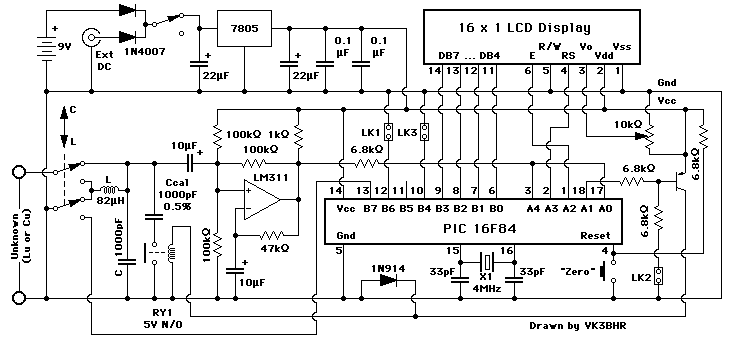
The oscillator design originally came from the AADE LC meter web page. It uses an LM311 comparator with positive feedback to make a parallel LC oscillator with digital output. It seems to oscillate readily over a wide range of L and C values. Hopefully, it follows the "well known formula for resonant frequency".
The frequency measuring part is a cut down version of the September 2002 Frequency Meter article from AR. The original idea for this came from the web pages of Eamon Skelton, EI9GQ.

Most of the components were mounted on a prototyping board (the sort that has copper donut lands spaced on a 0.1 inch grid.
Heres a link to a fuzzy photograph and an overly large sketch of my layout. Naturally, your layout will depend on available components.
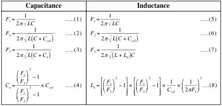
The program takes two measurements when "zeroed". First the oscillation frequency is measured using only the internal inductor and capacitor (F1). Then a standard capacitor (Ccal=1000pF +/- 1%) is added in parallel and the frequency is measured again (F2).
The program then goes into a repeating loop where it measures the frequency of the oscillator using the internal inductor and capacitor and whatever unknown external inductor or capacitor is connected (F3). Some serious maths (formulae 4 and 8) is performed each time to calculate the unknown external component value. This value is then scaled in engineering units and formatted for display.
After getting quite a few requests for the source code, I have decided to make it public. I am never going to get rich selling it. If you get rich, I don't want to know! (If you have fun with it, I do want to know ;-)
You have a choice of seven versions. (I would avoid the first, even though it works OK ;-)
| Assembler source code | Hex PIC code |
|---|---|
| lc004.txt an "early" version, only for the 16F84 | lc004.hex |
| lc628.asm ported to the 16F628 by Egbert, PA0EJH | |
| lc006.txt A version for both the 16F84 and the 16F628, incorporating modifications by Egbert, PA0EJH | lc006.hex for the 16F84 lc006b.hex for the 16F628 |
lcmeter.zip Andreas Winter has improved the program by:.
|
lcmeter.zip |
| lc006d.txt A "two range" version by Cristi Morariu Click here for a short article describing Christi's version, complete with pictures and diagrams. |
|
| LC006d32.txt A "32 bit" version by Cristi Morariu Click here for a copy of Cristi's email describing this version. |
|
| lc007.txt (25th. October 2005) A version for both the 16F84 and the 16F628. This incorporates error checking of ALL floating-point calculations. (Every single + - * & /) |
lc007a.hex for the 16F84 lc007b.hex for the 16F628 |
| LC Meter Version 2. (15th. November 2007) Revised hardware, using a 16F628 to replace the 16F84 and the LM311. Performance is no better or worse, but the circuit is marginally simpler AND there is a PC board layout for it and it has software calibration too! | |
You will also need two other files:
If you get rich selling it, I don't want to know!
If the frequency is too high (anything over 655.350KHz), the display will show "Over Range". If the oscillator isn't running, the display will show "0".
For best accuracy, the free running frequency should be 10% to 15% below 655KHz. If it is too close, it may accidentally overflow the PIC's internal 16 bit count. You may need to adjust the inductance to get get the frequency right..
A second link, LK2, connects the calibration capacitor. The oscillator should then run at about 394KHz.
A third link, from pin 10 of the PIC 16F84 to ground (LK3), caters for "badly behaved" displays. If your display only ever shows 8 characters (ie. no pF, nF or uH as appropriate) then try grounding pin 10 of the PIC.
The meter can be zeroed with an unknown component connected. For subsequent components, it then indicates the difference (+ or -) from the original component value. Great for matching parts!
When the unknown component has high Q (as you usually want in a tuned circuit) AND the L/C switch is set correctly, the prototype generally shows errors of less than 1%.
I checked the accuracy of the LC Meter against an old Marconi bridge, for capacitors of 33pF to 0.22uF. For inductors, I only checked values from 475uH down to 60uH. Below that value, the Marconi bridge was a bit "cranky".
While the LC Meter is self calibrating, errors depend a little on the components used in the oscillator LC tank (L and C on the circuit diagram) and on the "standard" capacitor (Ccal), which should be 1000pF to within 1% or better.
The worst errors occurred when using a ferrite bobbin style choke from a switchmode power supply for "L". Here the error was less than 1% for capacitors below 3300pF and 2% for inductors less than 475uH. The error climbed to 3% for 0.22uF capacitors.
Surprisingly, the best accuracy used a "moulded" choke scrounged from an old TV. Here, the error was less than 1% for capacitors less than 0.22uF and less than 1% for inductors less than 475uH.
In all cases, I used a 1000pF styroseal capacitor for the oscillator tank "C". A "greencap" would be a suitable substitute but a ceramic capacitor may not be a good choice. Some of these can have high losses.
I have no reason to suspect any strange non-linearities in the readings for low value components. Small component values are, in theory, directly proportional to frequency difference (when the part is added to the oscillator). The software inherently follows this proportionality. The only way I can verify this is to construct some small L/C tuned circuits and measure their resonant frequency - and I haven't got round to doing that yet.
It's now possible to design a tuned circuit, construct it and have it resonate on the right frequency first time, every time.
Please check this out before emailing me. It might just answer your question. I will put more answers here as they materialise (in answer to emailed questions ;-).